| Electronic Die |

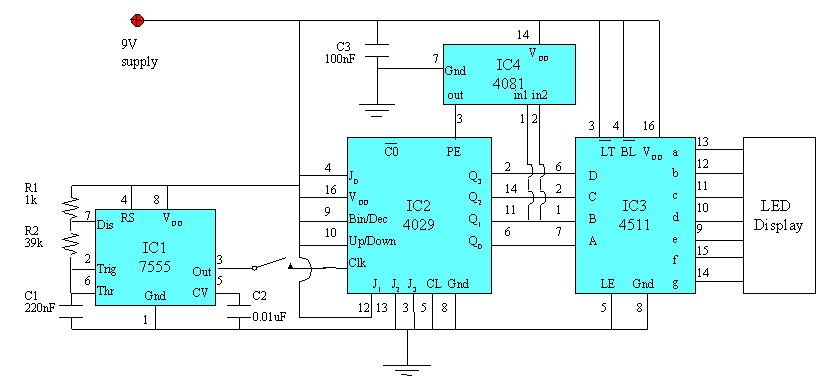
A dice is an essential item in board games that we play. Presented here is an electronic version of a dice which will give a pseudo random number on the LED display when the spring switch is pressed. This will definitely give a new twist to the traditional dice.
The circuit can be powered easily from a 9 V battery. IC1 is configured as a bistable multivibrator which produces a signal with a frequency of about 80Hz at pin 3. When the switch is closed, this signal will be fed into the clock input of IC2. IC2 is a type 4029 binary counter which is preset to state 1 by jamming inputs J0 to J3 while its output represents 1 of 6 pseudo random states after releasing the switch. The outputs from IC2 will pass through IC3, the LED display driver to display a random number in the LED display.
Counter output states 1 to 6 was chosen by attaching the outputs of
J1 and J2 to the input of a AND gate (IC 4). This ensures that when
state 7 is reached, IC2 will be preset to state 1. Hence, it will
cycle through states 1 through 6 when the switch is closed. Upon
releasing the switch, IC2 will remain in one of the six possible states.
As a single state correspond to a singe digit, one of the digits from 1
through 6 will be displayed. Have fun.
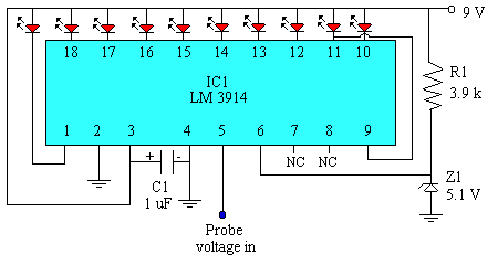
Often, we need a logic probe to show us the voltage at certain points. This circuit shown here will show the user the approximate logic voltage level by the LED display. As a voltage level of 5 V is commonly accepted as a high logic level, the circuit has been purposely designed so that at 5 V, the rightmost LED will light up. With each LED to the right reflecting a voltage drop of 0.5 V. This means that with a voltage level of 0.5 V, the leftmost LED will light up.
This circuit is built around the LM 3914 IC chip with the voltage reference
at pin 6 set to about 5 V by using the resistor and zener diode.
The circuit is configured to run in dot mode, but by connecting pin 9 to
pin 3 instead of pin 11, the circuit can be made to run in bar mode.
However, the current drain from the battery would be much greater in the
bar mode.