Circuit Symbol for an opamp

As you can see, the opamp consists of a non-inverting input (denoted with a + sign) and an inverting input (denoted with a - sign) as well as an output. Note that the power supplies to the opamp has been neglected.
Amplifiers are used primary for signal amplification so that the signals are suitable for further processing. This need for amplification arises due to the fact that transducers produce signals that are too "weak" which is normally in the microvolt(uV) or millivolt(mV) range.
By today, opamps have become very widespread and
are available at low prices from a large number of suppliers in IC package
form. One of the reasons for the popularity of the opamp is its versatility.
Circuit Symbol for an opamp 
As you can see, the opamp consists of a non-inverting
input (denoted with a + sign) and an inverting input (denoted with a -
sign) as well as an output. Note that the power supplies to the opamp
has been neglected.
Assumptions for an ideal opamp:
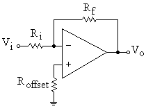
The output voltage of the inverting amplifier is the negative of the scaled input voltage. This means that if we inject a sine wave into the input, we get a scaled sine wave that is delayed by 180o.
Vo = ![]() where S = jw
where S = jw 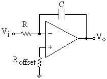
This amplifier has an integration function and therefore has "memory"
of past events.
Vo = ![]() Vi
Vi 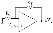
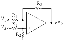
The differential amplifier gives a scaled voltage value of the difference
of the input signal. This is useful when we need to reject the common
signal (eg. noise) from a system.

The buffer amplifier is used primarily to act as a buffer between two different stages of a circuit. The two stages may have different impedance levels and the buffer will be used to connect them together.
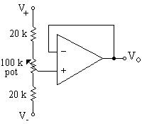
The circuit presented will produce a voltage level that can be adjusted by using the potentiometer. The range of the output voltage level is limited by the supply voltages which is commonly between +15V and -15V.
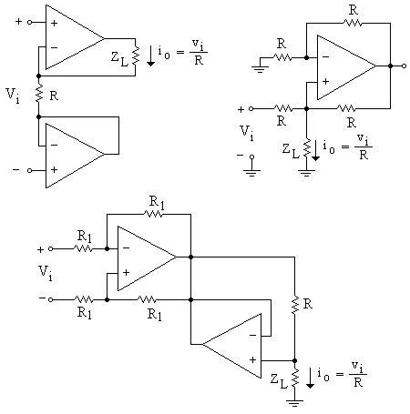
Shown above is three opamp configuration that will produce a voltage controlled current source to the load ZL.