Low-Pass Filter Stage
 
Low-Pass Filter 

High-Pass Filter  

Graphic Equaliser and Summer    

Buffer and Volume Control  


 For the filter stage, there are mainly two classes of filters available namely the passive and the active filters.  In general, passive filters utilises passive components such as resistors, inductors and capacitors to filter out unwanted frequency components and in general are used for high frequency applications.  On the other hand, active filters uses opamps together with passive components to produce bandpass and band reject filters without using inductors.  Active filters also provide a power gain not available  in passive filter circuits. 

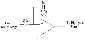
For simplicity, we can use a first order low-pass filter design.  The function of the low-pass filter is to let frequencies below cutoff frequency through and attenuate any frequency components greater than the cutoff frequency. 

lowpass_filter.gif 

The figure gives a first order low-pass filter with unity gain and a cutoff frequency of 20kHz. 


High-Pass Filter Stage


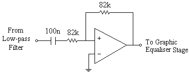
In the high-pass filter stage, we can use a first order high-pass filter design for simplicity.  The function of the high-pass filter is similar to that of the low pass filter.  It is to let frequencies above cutoff frequency through and attenuate any frequency components lower than the cutoff frequency. 
 
highpass_filter.gif 
 

The figure gives a first order high-pass filter with unity gain and a cutoff frequency of 20Hz. 


Graphic Equaliser and 
Summer Stage
 
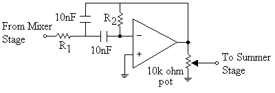
  A 5 band graphic equaliser can be used as an effective form of tone control.  Each band was implemented using a band pass filter.  In passive filters, there is usually a need for inductors to design a band pass filter.  Inductors are usually bulky and are prone to electromagnetic pickup, we would like to avoid using inductors as far as possible.  Active filters are used in this design as they do not need an inductor to implement a band pass filter.  Many different designs of band pass filters are available, and these can be easilty obtained from any reference books on filter design.  The following diagram shows a design utilising a single amplifier and a bridged-T network.  For a total of 5 bands, we would need 5 such amplifier configuration,  which is then summed together using a summer. 
equaliser_stage.gif
 
 
Centre Frequency
100Hz
330Hz
1kHz
3.3kHz
10kHz
Bandwidth
160Hz
300Hz
1040Hz
3560Hz
14920Hz
Frequency Range
20-180Hz
180-480Hz
480-1520Hz
1.52-5.1kHz
5.10-20kHz
Q-factor
0.625
1.1
0.962
0.927
0.67
R1
120k 
22k 
8.2k
2.7k 
1.2k 
R2 
180k 
100k 
30k 
8.2k 
2.2k 
 Gain at Centre Frequency
 0.78
2.4
1.85
1.72 
0.898
 
A calculator for the above butterworth filter is available for browsers supporting ActiveX technology.   Click Here
 

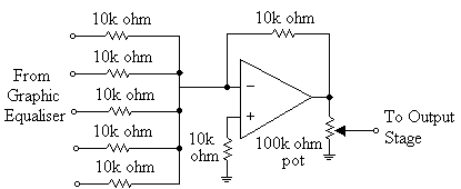
The output from the 5 bandpass filters are summed together using the summer amplifier configuration. 

summer_stage.gif


Buffer and Volume Control Stage
 
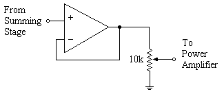
  The buffer and volume control stage forms the output stage of the preamplifier.  The buffer amplifier acts as an impedance transformer giving a low output impedance to prevent overloading by the power amlifier stage.  The volume control can be implemented using a 10k ohm logarithmic potentiometer.  A log potentiometer was chosen because our ears perceive volume in a logarithmic manner. 

 output_stage.gif


button_preamplifier_full_circuit.gifClick here to see the circuit diagram for the preamplifier
 
back_home1.gifBack to preamplifier development labs