|
|
| The preamplifier unit can be found in any basic audio amplifier
that is available in the market. The main purpose of the preamplifier
is to act as an intermediate voltage gain stage between the input signal
source and the power amplifier. Signal sources include the CD player, the
cassette player, the FM tuner and the microphone. Different type
of audio input signals will require different types of signal processing
such as different degree of amplification. Other functions of the
preamplifier include the filtering of noise and tone control.
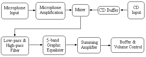
The entire preamplifier can be subdivided into various number of stages depending on the specifications given to the designer. Different stages include the microphone amplification stage, the mixer stage, the filter stage, the graphic equaliser stage, the summing stage and the output stage. One typical design diagram is shown below. In the above diagram, the preamplifier is divided into 6 stages: the
microphone amplification stage, the mixer stage, the low and high pass
filter stage, the graphic equaliser stage, the summing stage and the output
stage. For a basic stereo operation, it is necessary to duplicate
an entire circuit so as to seperate the input signal into a left and right
channel. For the more ambitious, additional sound effects can be
achieve through the use of IC chips that simulate the echo effect.
|
|
|
| As the input signal of most microphones are much
smaller than that of a CD input signal, the signal from the microphone
input may be overwhelmed by the CD input signal if it is connected directly
to the mixer stage. Thus, we need to increase the signal power of
the microphone using a microphone amplification stage.
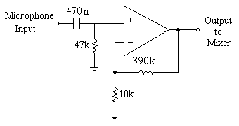
The maximum output signal from a microphone may vary from about 5mV to 100mV peak-to-peak depending on the microphone concerned. The output signal from a CD player is about 200mV to 500 mV peak-to-peak. In practise I found that a gain of 40 should suffice for most cases. We can use a non-inverting amplifier configuration with a gain of 40.
To couple the amplifier to the microphone, a 470nF capacitor can be used.
|
|
|
|
|
A CD buffer stage is used to provide a buffer between
the CD player input to the mixer stage. A simple design would be
to use a opamp configured as a voltage follower.
 |
|
|
|
|
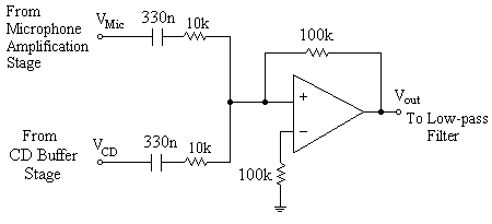
The mixer stage aims to sum up both the input signals from
the microphone and CD player. A summing amplifier is used for this
purpose. Capacitors are used to connect the mixer stage to the CD
buffer stage as well as the microphone amplification stage. In addition
to summation, the following design given below also gives a voltage gain
of 10.
The voltage gain can be adjusted to suit individual design by changing
the resistor values.
|
 Back
to preamplifier development labs


